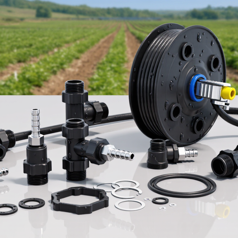
| Barbed Tape Start Connector | UV-stabilized polypropylene or glass-filled nylon; EPDM or silicone gasket | Commonly 16 mm, 17 mm, 22 mm and 5/8–7/8 in. tape sizes | Tape is pushed over serrated barbs and secured with a clamp or locking nut | Approximately 0.7–1.5 bar (10–22 psi), depending on tape wall thickness and clamp design | Multiple barbs, broad sealing shoulder, reinforced outlet and corrosion-free polymer body | Connecting drip tape to polyethylene header or submain pipe |
| Compression Tape Takeoff | Acetal, polypropylene or nylon body; EPDM sealing washer; stainless-steel or polymer nut | Most commonly used with 16–22 mm drip tape and polyethylene pipe outlets | Compression nut grips the tape or tube without requiring adhesive | Approximately 1.0–2.5 bar (15–36 psi), subject to pipe, gasket and nut specifications | Captive gasket, uniform compression, tool-free adjustment and reduced risk of tape pull-out | High-frequency installation and systems requiring quick replacement |
| Grommet Takeoff Connector | UV-resistant polypropylene or nylon; EPDM grommet; optional acetal locking insert | Drip tape connected to 16–25 mm polyethylene distribution pipe | A drilled header hole accepts a flexible grommet and barbed or threaded takeoff | Approximately 1.0–2.0 bar (15–29 psi), depending on hole size and header-wall thickness | Flexible grommet compensates for minor hole irregularities and helps prevent leakage | Retrofit manifolds and seasonal field layouts |
| Barbed Coupler or Joiner | Polypropylene or glass-filled nylon; optional EPDM O-ring or external clamp | Matching-diameter tape, typically 16, 17, 22 or 25 mm | Two tape ends are pushed onto opposing barbed sections | Approximately 0.7–1.5 bar (10–22 psi) | Long barbs, rounded entry profile, centered flow passage and optional locking clips | Repairing punctured tape and extending row lengths |
| Compression Coupler | Acetal or reinforced polypropylene; EPDM seal; polymer compression rings | Thin-wall and standard-wall tape where precise compression is required | Each tape end is inserted into a compression chamber and tightened by hand | Approximately 1.0–2.0 bar (15–29 psi), based on the fitting and tape rating | Even circumferential loading, replaceable seals and lower dependence on tape elasticity | Repeated repairs and installations using different tape wall thicknesses |
| Flush-End Valve | UV-stabilized polypropylene or nylon; EPDM diaphragm or sealing washer | Commonly 16–22 mm drip tape | Barbed or compression attachment with a manually operated flush outlet | Approximately 0.7–1.5 bar (10–22 psi) | Large flushing passage, positive shutoff, easy-grip handle and debris-tolerant flow path | Removing sediment from tape ends during startup and routine maintenance |
| Inline Shutoff Valve | Glass-filled nylon or polypropylene; EPDM or silicone seal components | Tape and microtube systems using 16–22 mm outlets | Barbed, compression or threaded connection installed in the row line | Approximately 1.0–2.5 bar (15–36 psi), depending on valve construction | Full-bore passage, quarter-turn handle, visible flow position and low-pressure sealing | Isolating individual rows and simplifying zone management |
| Threaded Adapter with Tape Barb | Polypropylene or reinforced nylon; EPDM O-ring; optional acetal locking nut | Tape connected to 1/2, 3/4 or 1 in. threaded manifolds and filters | Threaded pipe-side connection combined with a barbed tape outlet | Approximately 1.5–3.0 bar (22–44 psi), limited by the lowest-rated component | Positive thread engagement, O-ring sealing, reinforced shoulder and easy disassembly | Modular systems requiring filters, regulators, valves or multiple zones |

.svg)