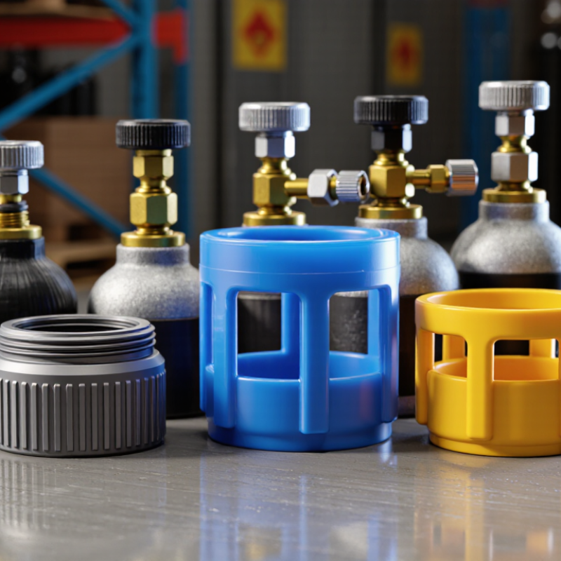
High-pressure oxygen cylinders
Used for medical, laboratory, or industrial oxygen service. | CGA 540 is a common reference in North America. The valve outlet standard identifies the valve; it does not determine the protective-cap thread. | Confirm cylinder neck-ring thread, outside diameter, valve height, and whether the valve protection cap is intended for oxygen service. | Cap internal diameter should normally provide approximately 2–4 mm of total clearance over the neck-ring diameter. Internal height should extend at least 10–20 mm above the highest valve component. | Steel or impact-resistant engineered polymer with a vented design and no material that can contaminate oxygen equipment. | Install by hand after confirming the valve is closed and the cylinder is upright. Keep threads clean, dry, and free from oil or grease. | The cap contacts the valve handwheel, outlet, pressure-relief device, or cylinder shoulder; or it requires force to start threading. |
Inert and shielding gas cylinders
Typical gases include nitrogen, argon, helium, and mixed shielding gases. | CGA 580 is commonly used for several inert-gas applications in North America, but local valve standards may differ. | Match the protective-cap interface to the cylinder neck ring rather than relying only on the gas name or outlet connection. | Use a cap that fully covers the valve and allows free movement without side loading. A practical target is at least 1 mm radial clearance from fixed valve components. | Impact-resistant steel or polymer with reinforced ribs, rounded edges, and corrosion-resistant hardware. | Align the thread vertically and tighten only until securely seated. Do not use a pipe wrench or extension bar unless specifically required by the cap design. | The cap rocks excessively, bottoms out before engaging the thread, or leaves any part of the valve exposed to a likely impact. |
Carbon dioxide cylinders
Used for beverage dispensing, laboratories, and industrial processes. | CGA 320 is a common North American reference for carbon dioxide service. | Check the cylinder neck-ring dimensions and the valve’s relief-device location. Carbon dioxide cylinders may have different shoulder and valve arrangements from other gas cylinders. | The cap must not obstruct the pressure-relief device. Maintain the cap manufacturer’s specified clearance around the valve and relief components. | Vented, corrosion-resistant construction with drainage openings to reduce moisture accumulation. | Keep the cylinder secured against tipping before fitting the cap. Check that the cap remains stable during normal handling and transport. | Vent openings are blocked, the cap presses against the relief device, or condensation and debris cannot drain from the cap. |
Flammable gas cylinders
Includes many fuel-gas and combustible-gas applications. | Valve outlet connections vary by gas, country, and cylinder design; the outlet type must be verified from the cylinder marking or documentation. | Confirm the cap is approved for the specific cylinder, gas service, temperature range, and hazardous-area handling requirements. | The cap must prevent impact without trapping gas around the valve. Fit should be secure but removable without striking, twisting, or damaging the valve. | Non-sparking or suitably rated materials where required, with rounded impact surfaces and adequate ventilation. | Remove ignition sources, verify the valve is closed, and follow the applicable cylinder-handling and hazardous-material procedures. | The cap is unapproved for the gas service, creates a sealed pocket around the valve, or can generate damaging impact or friction during installation. |
Medical or portable cylinders
Small cylinders where low weight and frequent handling are important. | Valve outlet and neck-ring configurations vary widely by cylinder size and regional standard. | Measure the actual cylinder; do not select a cap from the cylinder volume alone. Check compatibility with handles, carts, regulators, and carrying cases. | Allow enough clearance for easy fitting while preventing noticeable wobble. The cap should not add an obstruction to the cylinder’s normal carrying points. | Lightweight impact-resistant polymer or thin-gauge corrosion-resistant metal with smooth, cleanable surfaces. | Fit the cap before moving the cylinder. Verify that the cap remains attached during lifting, cart movement, and storage. | The cap interferes with the regulator, carrying handle, cart strap, or required visual inspection of the cylinder label. |
Large industrial cylinders or bundles
Used in storage racks, production areas, and transport frames. | Outlet standards depend on gas and jurisdiction; large cylinders may also use different neck-ring sizes than smaller cylinders containing the same gas. | Check cap load rating, lifting restrictions, cylinder height, rack clearance, and compatibility with the bundle frame. | The cap should remain fully seated under normal vibration and handling, while leaving sufficient clearance for rack members and restraints. | Heavy-duty steel or reinforced polymer with impact ribs, drainage, replaceable fasteners, and a corrosion-resistant finish. | Secure the cylinder or bundle before installation. Use designated lifting points only; the protective cap should not be used as a lifting handle unless rated for that purpose. | The cap is used to lift the cylinder without a rated lifting feature, collides with the frame, or cannot be removed for inspection without moving the cylinder unsafely. |

.svg)