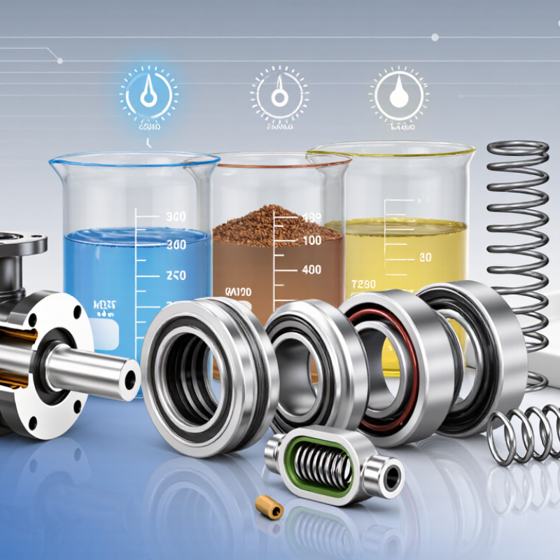
| Basic Definition | A pusher seal is a mechanical seal in which a dynamic elastomer secondary seal moves axially along the shaft or sleeve. | The moving secondary seal compensates for normal face wear, shaft movement, and small dimensional changes. | It provides a compact and widely used sealing arrangement for pumps and other rotating equipment. | Confirm that the equipment shaft, sleeve, and seal chamber are suitable for axial movement of the secondary seal. |
| How It Works | Primary sealing occurs at the rotating and stationary seal faces. The elastomer secondary seal limits leakage around the shaft or sleeve. | A spring or spring set applies closing force while hydraulic pressure helps maintain contact between the seal faces. | Stable face contact is necessary to control leakage without creating excessive friction and heat. | Review pressure, speed, temperature, lubrication, and face-loading conditions together rather than separately. |
| Typical Equipment | Commonly used in centrifugal pumps, process pumps, mixers, agitators, and selected compressors. | Suitable for many general-purpose water, chemical, utility, and process-fluid services when correctly specified. | Equipment geometry and operating conditions determine whether a standard pusher arrangement is appropriate. | Measure shaft diameter, seal-chamber dimensions, mounting length, and rotating direction before selection. |
| Primary Seal Faces | The faces form the main sliding seal and are normally manufactured from hard and/or wear-resistant materials. | Common combinations include carbon versus silicon carbide, carbon versus tungsten carbide, and silicon carbide versus silicon carbide. | Face pairing affects wear, friction, heat generation, chemical resistance, and dry-running tolerance. | Choose the pair according to fluid abrasiveness, lubrication, corrosion risk, pressure, and shaft speed. |
| Secondary Seal Material | The elastomer seals the gap between the seal components and the shaft or sleeve. | Common choices include EPDM, NBR, FKM, and FFKM, with compatibility depending on the fluid and temperature. | An incompatible elastomer can swell, harden, crack, lose elasticity, or cause leakage. | Check chemical compatibility, minimum and maximum temperature, concentration, cleaning chemicals, and exposure time. |
| Spring Arrangement | Springs provide the mechanical closing force that keeps the seal faces together. | Single-spring designs are simple; multi-spring designs distribute loading more evenly and can suit higher-performance applications. | Spring design influences face loading, balance, fouling sensitivity, and installation orientation. | Consider fluid solids, crystallization, corrosion, speed, pressure, and whether the spring is inside or outside the process fluid. |
| Balanced or Unbalanced Design | Balance describes the relationship between hydraulic pressure and the effective face area loaded by that pressure. | Balanced seals generally reduce hydraulic closing load and are often preferred for higher pressure or lower-lubricity services. | Correct balance helps limit heat and wear at the seal faces. | Use the equipment pressure and seal design limits to verify the required balance ratio; do not select by pressure alone. |
| Pressure | Pressure acts across the seal faces and can affect leakage, heat generation, and face stability. | Allowable pressure is design-specific and depends on speed, face materials, balance, temperature, and seal chamber geometry. | A seal rated for a certain pressure at low speed may have a lower allowable pressure at higher speed. | Specify normal, maximum, start-up, shutdown, and upset pressure—not only the average operating pressure. |
| Temperature | Temperature affects elastomer life, lubricant film stability, face distortion, and the physical properties of the fluid. | Temperature limits must be checked for every component, especially the secondary seal and face materials. | Excessive temperature can accelerate wear, degrade elastomers, and vaporize the process fluid at the faces. | Record operating, start-up, cleaning, and transient temperatures and compare them with material limits. |
| Shaft Speed | Rotational speed influences sliding velocity, frictional heat, vibration sensitivity, and dynamic runout. | Higher speed generally requires better face tracking, suitable balance, accurate installation, and effective heat removal. | High sliding speed can cause face overheating even when pressure is moderate. | Provide operating speed, maximum overspeed, shaft diameter, and any variable-speed drive information. |
| Fluid Lubrication | The seal faces normally rely on a very thin fluid film to reduce direct contact and control wear. | Clean, lubricating liquids are generally easier to seal than hot, volatile, gas-like, or poorly lubricating fluids. | Loss of the fluid film can produce rapid face damage and thermal cracking. | Determine viscosity, vapor pressure, solids content, crystallization tendency, and whether the liquid can flash at the faces. |
| Solids and Abrasives | Suspended particles can enter the sliding interface or damage the dynamic secondary seal. | Hard face materials, proper flushing, and a suitable spring arrangement may improve service in abrasive fluids. | Solids can scratch faces, block springs, accelerate wear, and create leakage paths. | Document particle size, hardness, concentration, settling behavior, and whether solids are present during start-up. |
| Cleanliness and Crystallization | Some fluids form deposits when exposed to air, cooling, evaporation, or temperature changes. | A seal design with protected springs or an appropriate flush arrangement may be required for crystallizing services. | Deposits can restrict axial movement and prevent the seal faces from closing correctly. | Assess drying, polymerizing, crystallizing, and sticky-fluid behavior during normal operation and shutdown. |
| Installation Tolerance | Seal performance depends on correct dimensions, perpendicularity, concentricity, surface finish, and shaft condition. | The sleeve or shaft should be free from burrs, sharp edges, deep scratches, and excessive runout. | Installation errors can damage elastomers, distort faces, or cause premature leakage. | Follow the seal drawing for setting length, end-play, runout, chamber dimensions, and tightening sequence. |
| Maintenance Needs | Pusher seals contain wear components and elastomers that may eventually require replacement. | Routine inspection should focus on leakage trend, vibration, temperature, flush flow, and equipment alignment. | Early detection can prevent secondary damage to shafts, sleeves, bearings, and seal chambers. | Establish a leakage and condition-monitoring baseline after installation and investigate sudden changes. |
| When to Consider an Alternative | A different seal architecture may be more suitable when the process is highly abrasive, gas-like, very hot, or prone to deposit formation. | Non-pusher bellows designs, cartridge arrangements, dual seals, or specialized systems may be considered depending on the duty. | No single seal type is optimal for every pressure, temperature, speed, and fluid combination. | Escalate the application for engineering review when operating limits overlap, dry running is possible, or leakage consequences are severe. |

.svg)