| Primary Function | Project piping specification and structural design basis | Transfers axial pressure thrust, thermal loads, and selected bending loads into a concrete anchor block or structural support. | The flange should be treated as part of a complete restraint system rather than as a standard pressure flange alone. | Buried water lines, transmission pipelines, pump discharge lines, and directional changes. |
| Dimensional Standard | ASME B16.5 | Covers pipe flanges and flanged fittings from NPS 1/2 through NPS 24, including dimensions, tolerances, pressure-temperature ratings, materials, and marking. | Use the selected standard flange dimensions for the pipe connection, while separately checking the anchor collar, plate, welds, and block interface. | Industrial and municipal piping within the standard NPS 1/2–24 size range. |
| Large-Diameter Standard | ASME B16.47 | Covers large-diameter steel flanges from NPS 26 through NPS 60 and includes pressure-temperature ratings, dimensions, materials, and marking requirements. | Large anchor flanges generally require project-specific verification of bolt circle, plate thickness, weld details, and local stresses. | Large water transmission, cooling-water, oil, gas, and process pipelines. |
| European Flange System | EN 1092-1 | Specifies circular steel flanges with designated PN pressure classes, including dimensions, facing types, bolt patterns, materials, and marking. | Do not mix EN and ASME bolt patterns or facing dimensions unless the transition has been specifically engineered and verified. | European-design water, energy, chemical, and general industrial pipelines. |
| Pipeline Flange Practice | MSS SP-44 | Provides requirements for steel pipeline flanges, including dimensions, pressure classes, materials, and marking for pipeline service. | Useful when the pipeline specification calls for pipeline-specific flange geometry, but the restraint structure still needs independent engineering. | Long-distance steel pipelines and pipeline valve or fitting connections. |
| Pressure Rating | Applicable flange standard and design code | ASME systems commonly use Class ratings such as 150, 300, 600, and 900; EN systems commonly use PN designations such as PN10, PN16, PN25, and PN40. | The allowable pressure depends on material, temperature, flange class, gasket, bolts, corrosion allowance, and design code. A nominal class is not a universal pressure value. | Water, oil, gas, steam, and process systems with documented pressure-temperature conditions. |
| Facing and Sealing | ASME B16.5, ASME B16.47, EN 1092-1, or project specification | Common facing arrangements include raised face, flat face, and ring-type joint configurations, depending on the governing standard and service. | Gasket type, surface finish, bolt preload, flange rotation, and pipe alignment must be compatible with the selected facing. | Flanged joints requiring leakage control under pressure or temperature cycling. |
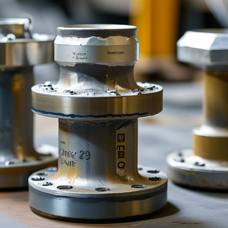
| Anchor Geometry | Approved fabrication drawing and structural calculation | Typical features include a flange hub or weld-neck connection, an enlarged anchor plate or collar, and load-transfer surfaces embedded in concrete or attached to steelwork. | Plate diameter, thickness, stiffeners, shear keys, and weld size are determined from calculated axial, shear, bending, and torsional loads. | Fixed points, buried restraints, valve chambers, pump stations, and pipeline crossings. |
| Material Selection | Material standard specified by the applicable flange code and project documents | Carbon steel is widely used; low-temperature, stainless, alloy, or corrosion-resistant materials may be selected for specific service conditions. | Check strength, toughness, weldability, corrosion resistance, fluid compatibility, and galvanic interaction with connected components. | Ambient, low-temperature, corrosive, high-temperature, and buried pipeline environments. |
| Welding and Fabrication | Approved welding procedure, qualified personnel, and project quality plan | Fabrication may involve butt welds, fillet welds, reinforcing ribs, machined sealing faces, and dimensional inspection of the finished assembly. | Weld design should account for pressure loads, restraint loads, fatigue, heat-affected zones, distortion, and access for inspection. | Factory-fabricated assemblies requiring traceable welding and inspection records. |
| Inspection and Testing | Project inspection and test plan; applicable pressure-testing and welding requirements | Typical controls include material certificates, dimensional checks, visual examination, weld nondestructive testing where specified, surface inspection, and pressure testing of the pipeline system. | Inspection scope should cover the pressure boundary and the load-bearing anchor structure, not only the flange face. | Critical transmission, process, energy, and municipal infrastructure projects. |
| Corrosion Protection | Project coating, lining, cathodic-protection, or corrosion-control specification | Possible systems include external coating, internal lining, paint, wrapping, or cathodic protection, selected according to soil, fluid, temperature, and exposure conditions. | Protect machined faces, weld zones, buried surfaces, and crevices while preserving gasket contact and bolt installation requirements. | Buried pipelines, marine installations, wastewater systems, and chemically aggressive services. |

.svg)