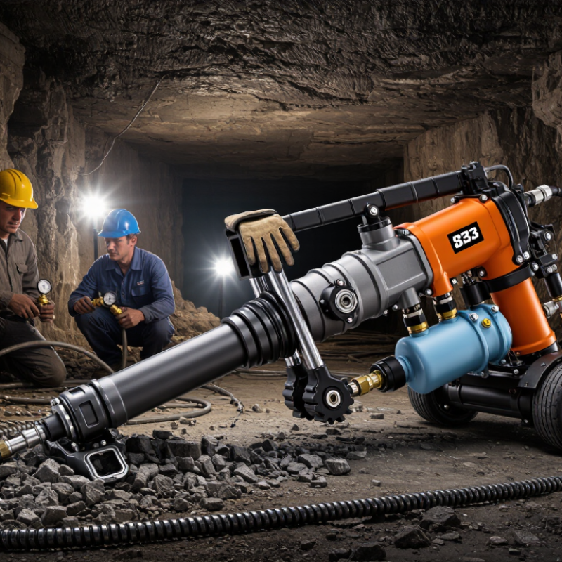
| Rock Drill | Drilling application | Hand-held or air-leg-mounted percussion drilling | Select an S83 configuration for quarrying, mining, tunneling, construction, and secondary rock breaking where compressed-air operation is available. |
| Rock Drill | Typical bore diameter | Approximately 34–42 mm | Use the lower end for faster drilling in softer rock and the upper end for larger blast-hole or anchor-hole requirements. Actual diameter depends on the bit and rock formation. |
| Rock Drill | Typical drilling depth per rod | Approximately 1.0–2.0 m | Choose drill-rod length according to the air-leg stroke, required hole depth, working clearance, and the need to remove rods safely. |
| Rock Drill | Rated working air pressure | About 0.63 MPa (6.3 bar) | The compressor and air network should maintain the required pressure at the drill inlet while the machine is operating. Avoid exceeding the drill manufacturer’s rated pressure. |
| Rock Drill | Typical free-air consumption | Approximately 55–70 L/s at rated pressure | Size the compressor using the drill’s actual air-consumption rating plus a reserve of approximately 20–30% for hose losses, leakage, simultaneous tools, and changing rock conditions. |
| Rock Drill | Impact frequency | Approximately 2,000–2,500 blows/min | A higher impact rate may improve penetration in suitable rock, but excessive feed force, dull bits, or inadequate air volume can reduce performance and increase wear. |
| Rock Drill | Air-leg mounting | Front and rear mounting points with a pivoting support arrangement | Confirm that the air-leg brackets, pins, mounting holes, and drill centerline match. The leg must support the drill without binding throughout its full extension. |
| Air Leg | Recommended leg type | Telescopic pneumatic air leg for rock-drill feed control | Use a leg designed for the S83 mounting pattern and operating pressure. A general-purpose pneumatic cylinder is not automatically suitable for drilling vibration or feed loads. |
| Air Leg | Typical usable extension | Approximately 1.2–1.8 m, depending on leg model | Select the stroke according to roof height, bench height, hole angle, and operator access. Keep sufficient retraction length for transport and positioning. |
| Air Leg | Feed-force requirement | Adjustable, generally sufficient to maintain steady bit contact without stalling | The leg should provide controlled thrust rather than maximum force only. Excessive feed force can jam the bit, bend rods, overload the chuck, and accelerate wear. |
| Air Leg | Control arrangement | Separate or integrated valves for extension, retraction, and feed adjustment | Prefer controls that allow slow positioning and smooth feed adjustment. A shut-off valve should isolate the leg before maintenance or relocation. |
| Compressed Air | Recommended compressor capacity | At least 70–90 L/s free-air delivery for one drill, subject to actual consumption | Use the compressor’s delivered-air rating at the working pressure, not only its motor power or theoretical displacement. Add capacity when other pneumatic tools operate simultaneously. |
| Compressed Air | Air hose internal diameter | Commonly 19–25 mm for the main hose | Use a larger diameter for long runs or high air demand. Minimize sharp bends, unnecessary reducers, and excessive hose length to limit pressure drop. |
| Compressed Air | Hose working-pressure rating | At least 1.5 times the maximum operating pressure | Select hose, couplings, and whip checks with compatible pressure ratings. Inspect for cuts, abrasion, loose fittings, and damaged safety cables before use. |
| Air Treatment | Moisture control | Water separator or aftercooler with regular draining | Remove condensate before it reaches the drill. Water in the air line can cause corrosion, valve sticking, lubricant washout, and freezing in cold conditions. |
| Air Treatment | Air-line lubrication | In-line pneumatic oiler installed near the drill | Use the lubricant specified for pneumatic percussion equipment and adjust the feed rate according to the maintenance manual. Do not mix incompatible oils. |
| Drilling Tools | Drill-rod shank compatibility | Common short-hole shank sizes include approximately 22 × 108 mm; verify the exact S83 chuck specification | The shank diameter, length, collar geometry, and flushing passage must match the chuck and retaining mechanism. Never force an incompatible rod into the drill. |
| Drilling Tools | Bit selection | Threaded or integral button bit selected for the rod system and target hole diameter | Match bit diameter and carbide design to rock hardness, abrasiveness, fracturing, and flushing conditions. Replace bits when penetration rate falls or excessive wear appears. |
| Flushing | Cuttings removal | Compressed-air flushing; water-assisted flushing where site conditions permit | Maintain sufficient flushing flow to clear cuttings without creating unsafe dust or water hazards. Use dust suppression or wet drilling controls when required by the site. |
| Safety | Required operator protection | Safety helmet, eye protection, hearing protection, gloves, protective footwear, and respiratory protection where required | Follow the site risk assessment and applicable occupational-safety requirements. Keep personnel clear of the rotating rod, exhaust, hose connections, and unstable rock. |
| Inspection | Pre-operation checks | Inspect mounting pins, hoses, couplings, valves, lubrication, drill rods, bits, and air pressure | Do not operate with damaged hoses, loose fasteners, cracked brackets, leaking valves, worn retainers, or a misaligned air leg. Verify the drill is securely supported before starting. |
| Final Selection | Best-fit configuration | S83 drill + matched telescopic air leg + adequately sized compressor + treated air supply + compatible rod and bit system | Before purchase, compare the nameplate data, mounting dimensions, air consumption, pressure, shank specification, leg stroke, hose connection size, and local service requirements. |

.svg)