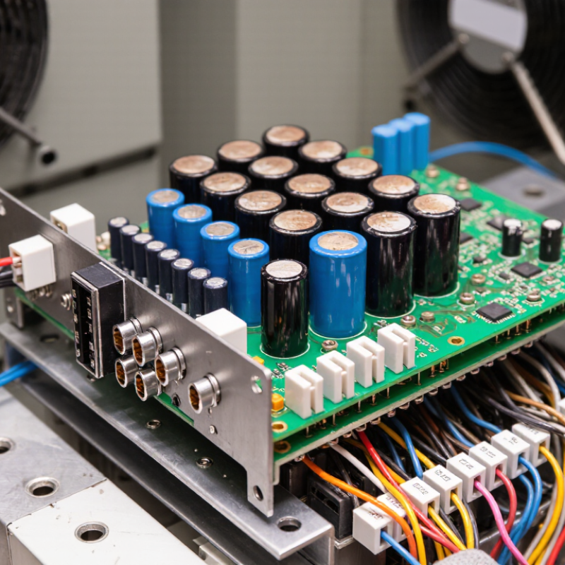
| Main Control PCB | Runs the inverter control logic, speed regulation, acceleration and deceleration profiles, and protection algorithms. | Microcontroller or processor, memory, analog inputs, digital inputs, PWM outputs, current feedback, and voltage feedback. | Requires stable low-voltage power, correct firmware compatibility, adequate grounding, and protection from electrical noise. | Match the inverter series, rated input and output configuration, control method, firmware version, connector layout, and communication requirements. | No display, incorrect speed control, unexpected trips, loss of parameter memory, or failure to start. |
| Gate Driver PCB | Converts low-power control pulses into properly timed gate-drive signals for the inverter switching devices. | Isolation circuits, gate-drive transformers or isolators, bootstrap circuits, desaturation protection, and gate resistors. | Must provide electrical isolation, correct gate voltage, suitable switching timing, and protection against short circuits. | Verify compatibility with the installed IGBT or power module, switching frequency, isolation rating, connector position, and protection scheme. | Overcurrent trips, phase loss, abnormal motor noise, immediate shutdown, or damaged switching devices. |
| Power Interface PCB | Routes and monitors connections between the rectifier, DC link, braking circuit, inverter bridge, and control electronics. | Bus-voltage sensing, current shunts or sensors, pre-charge interface, relay drivers, braking resistor interface, and terminal connectors. | Must withstand the applicable voltage, current, temperature, vibration, and clearance requirements of the drive. | Check voltage class, current rating, creepage and clearance, terminal arrangement, sensor type, and braking hardware compatibility. | DC-bus overvoltage or undervoltage faults, pre-charge failure, inaccurate current readings, or braking malfunction. |
| Power Supply PCB | Generates regulated low-voltage rails for the control board, gate drivers, sensors, fans, and interface circuits. | Switch-mode supply, transformers, rectifiers, voltage regulators, fuses, feedback circuits, and protection components. | Output voltage stability, isolation, thermal performance, and adequate protection against surges are essential. | Match input range, output rails, power capacity, isolation requirements, connector pinout, and mounting dimensions. | Blank display, repeated resets, communication loss, fan failure, or multiple low-voltage fault codes. |
| Interface and Keypad PCB | Provides local operation, parameter entry, status indication, and fault-code display. | Push buttons, membrane keypad, display module, indicator LEDs, potentiometer interface, and serial connection. | Needs mechanical compatibility, clear display visibility, reliable connector contact, and suitable enclosure protection. | Confirm display type, keypad layout, cable length, connector orientation, enclosure fit, and supported parameter functions. | Unresponsive keys, missing segments, intermittent display, or inability to access parameters. |
| Communication PCB | Connects the VFD to a PLC, industrial controller, supervisory system, or networked automation system. | Serial transceivers, Ethernet interface circuits, isolated communication channels, termination components, and status LEDs. | Requires correct protocol settings, cable shielding, termination, isolation, and electromagnetic compatibility practices. | Match the communication protocol, connector type, baud rate or network speed, isolation level, addressing method, and software support. | Communication timeout, corrupted data, intermittent connection, or inability to read and write parameters. |
| Cooling and Protection PCB | Controls cooling fans and monitors thermal, airflow, door, and other protective conditions. | Fan drivers, temperature sensors, thermal switches, airflow inputs, relays, and alarm circuits. | Performance depends on correct sensor characteristics, clean airflow, fan voltage, and ambient temperature limits. | Check sensor type, fan voltage, connector arrangement, alarm logic, environmental rating, and physical location. | Overtemperature alarms, fan-not-running faults, nuisance trips, or reduced output capability. |

.svg)