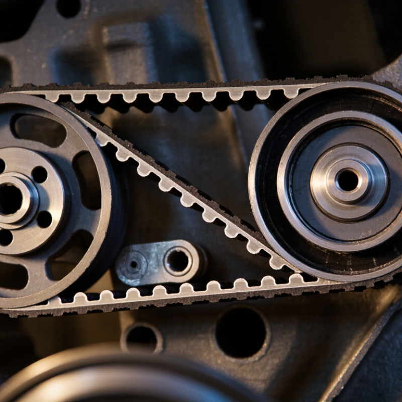
| Basic Definition | Toothed flexible drive belt | A rubber timing belt is a flexible belt with molded teeth on its inner surface. The teeth engage with matching grooves on timing pulleys. | It transfers motion through positive tooth engagement rather than relying mainly on friction. |
| Primary Function | Synchronous power transmission | The belt keeps the driving pulley and driven pulley rotating in a fixed timing relationship. | It is suitable for applications that require accurate speed synchronization and repeatable positioning. |
| Main Components | Tooth layer, tensile cords, and backing | The tooth layer provides engagement, the tensile cords carry most of the pulling load, and the outer backing protects the belt from wear and environmental exposure. | Each layer contributes to torque capacity, dimensional stability, flexibility, and service life. |
| Common Rubber Materials | Neoprene and hydrogenated nitrile rubber | Neoprene is used in many conventional timing belts. Hydrogenated nitrile rubber is selected when improved resistance to heat, oil, ozone, and aging is required. | The appropriate rubber compound depends on temperature, contamination, speed, load, and required service life. |
| Tensile Cord Materials | Fiberglass, aramid, or steel cords | Fiberglass cords provide good dimensional stability and flexibility. Aramid cords offer high strength with low elongation and low mass. Steel cords provide high tensile capacity but may require suitable handling and pulley design. | Cord selection affects allowable tension, stretch resistance, bending performance, and operating speed. |
| Tooth Profiles | Trapezoidal and curvilinear profiles | Trapezoidal teeth are widely used for general synchronous drives. Curvilinear profiles generally provide smoother engagement and improved load distribution when correctly matched to the pulley. | The belt tooth profile must match the pulley tooth profile; mismatched profiles can cause noise, wear, or tooth skipping. |
| Operating Principle | Positive engagement | As the driving pulley rotates, its teeth push the belt teeth forward. The belt then drives the teeth of the driven pulley at the same pitch. | Under correct installation and loading, the system has little or no normal slip compared with friction-driven belts. |
| Speed Ratio | Determined by pulley tooth counts | The ideal speed relationship is based on the number of teeth on each pulley: driven speed = driving speed × driving pulley teeth ÷ driven pulley teeth. | Changing pulley tooth counts changes output speed while preserving synchronous operation. |
| Torque Capacity | Controlled by belt width, pitch, and construction | Torque capacity depends on belt width, tooth pitch, tensile cord strength, tooth engagement, pulley size, speed, and operating conditions. | A wider belt or stronger construction may carry more load, but the complete drive must still be correctly sized. |
| Pitch | Distance between corresponding tooth positions | Belt pitch is the distance from one tooth center to the next measured along the pitch line. Common metric pitches include 2 mm, 3 mm, 5 mm, 8 mm, and 14 mm, although other sizes are available. | The belt pitch and pulley pitch must be identical for proper engagement. |
| Advantages | Accurate, clean, and efficient operation | Timing belts normally operate without lubrication, provide accurate synchronization, and produce less maintenance mess than chain drives. | They are commonly used where cleanliness, low maintenance, and controlled timing are important. |
| Limitations | Sensitivity to installation and environment | Excessive tension, insufficient tension, pulley misalignment, contamination, shock loading, and operation beyond the belt’s rated conditions can cause premature failure. | Correct tension, alignment, guarding, and environmental compatibility are essential for reliable service. |
| Compared with V-Belts | Synchronous versus friction drive | A timing belt uses teeth for positive engagement, while a V-belt transmits power mainly through friction between its sidewalls and pulley grooves. | Timing belts are preferred when slip cannot be tolerated; V-belts are often selected for simpler, more tolerant friction-drive systems. |
| Compared with Roller Chains | Lower lubrication needs and lower mass | Rubber timing belts are generally lighter and do not normally require oil lubrication. Roller chains can handle specific high-load conditions but require lubrication and may produce more noise. | The choice depends on load, temperature, contamination, shock, space, maintenance requirements, and design standards. |
| Typical Applications | Synchronized motion systems | Applications include positioning equipment, conveyors, packaging machinery, textile equipment, robotics, printers, pumps, and internal combustion engine timing systems. | These applications benefit from synchronized rotation or controlled linear movement. |
| Maintenance Checks | Inspection, tension, and alignment | Routine checks should look for tooth wear, cracking, fraying, exposed cords, oil or chemical contamination, abnormal noise, and pulley misalignment. | Replacing a belt according to the equipment manufacturer’s maintenance schedule helps reduce the risk of unexpected failure. |
| Failure Modes | Tooth shear, tooth skipping, and cord fatigue | Common failures include tooth wear, tooth shear, tooth skipping, edge wear, cracking, delamination, and tensile cord breakage. | Failure causes often include overload, incorrect tension, inadequate pulley engagement, contamination, misalignment, or aging. |

.svg)