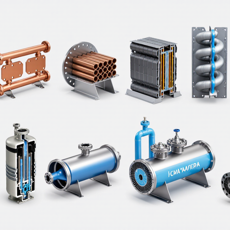
| 1 | Fixed-Tubesheet, Single-Pass Shell-and-Tube | Straight tubes expanded or welded into stationary tube sheets; shell encloses the tube bundle. | Water through tubes; vapor condenses on the shell side. | 0.8–2.2 m/s | 20–80 kPa | 19–25 mm OD | 100 kW–20 MW | General-purpose refrigerant, process-vapor, and utility-water condensing. | The shell side is difficult to mechanically clean; differential thermal expansion must remain limited. |
| 2 | Fixed-Tubesheet, Two- or Four-Pass Shell-and-Tube | Straight-tube bundle with partitioned channel heads that route water through multiple passes. | Counterflow or cross-counterflow with multiple tube passes. | 1.0–2.8 m/s | 40–140 kPa | 16–25 mm OD | 200 kW–30 MW | Installations needing higher water-side heat-transfer coefficients and a compact footprint. | More passes increase pressure drop and can create uneven flow distribution if the channel design is poor. |
| 3 | U-Tube Shell-and-Tube Condenser | Each tube bends into a U-shape, with both tube ends fixed in one tube sheet. | Two-pass water flow through the U-tubes. | 0.9–2.5 m/s | 35–120 kPa | 19–25 mm OD | 300 kW–25 MW | High-temperature service where tube-to-shell thermal expansion is significant. | The U-bend region is difficult to clean internally, and tube replacement is less convenient. |
| 4 | Floating-Head Shell-and-Tube Condenser | One tube sheet is fixed while the opposite tube sheet is free to move inside a removable head. | One-, two-, or four-pass tube-side water flow. | 0.8–2.6 m/s | 30–130 kPa | 19–25 mm OD | 500 kW–40 MW | Large process condensers requiring bundle removal and tolerance of substantial temperature differences. | Higher cost, larger envelope, and more sealing components than fixed-tubesheet designs. |
| 5 | Removable-Bundle Shell-and-Tube Condenser | A complete tube bundle can be withdrawn from the shell for inspection, cleaning, or replacement. | Usually two- or four-pass water flow with shell-side vapor condensation. | 1.0–2.7 m/s | 40–150 kPa | 19–32 mm OD | 1–50 MW | Cooling-water systems with high fouling risk or strict maintenance requirements. | Requires adequate tube-pulling space and structural support for the removable bundle. |
| 6 | Vertical Downflow Shell-and-Tube Condenser | Vertical shell with water tubes arranged for vapor flow downward and condensate drainage by gravity. | Water generally upward or downward; vapor and condensate move downward on the shell side. | 0.7–2.0 m/s | 20–90 kPa | 19–25 mm OD | 500 kW–30 MW | Systems with limited floor area and applications benefiting from reliable condensate drainage. | Tube-side venting, water distribution, and access height must be carefully considered. |
| 7 | Horizontal Surface Condenser with Enhanced Tubes | Horizontal shell-and-tube body using internally enhanced or externally enhanced tubes to increase heat-transfer area. | Cooling water inside tubes; steam or refrigerant condenses outside the tubes. | 1.2–3.0 m/s | 50–180 kPa | 16–25 mm OD | 1–100 MW | Large steam-cycle and process-condensing systems where shell volume must be minimized. | Enhanced surfaces may be more sensitive to fouling, plugging, and unsuitable mechanical cleaning methods. |
| 8 | Straight Double-Pipe Condenser | One pipe is installed concentrically inside a larger pipe, creating separate fluid passages. | Preferably countercurrent; vapor condenses in the annulus or inner pipe. | 0.8–2.5 m/s | 20–100 kPa | 25–100 mm OD inner tube | 5–300 kW | Small refrigeration packages, laboratory equipment, and modular process skids. | The design becomes uneconomical for large duties because many parallel units may be required. |
| 9 | Hairpin Double-Pipe Condenser | Two concentric pipes connected by a return bend, forming a compact two-pass exchanger. | Countercurrent flow in the active legs; condensate normally drains toward the outlet. | 1.0–3.0 m/s | 40–160 kPa | 25–150 mm OD inner tube | 20 kW–1 MW | Compact packaged systems and services requiring close temperature approaches. | Return bends increase local pressure loss and can complicate drainage and mechanical cleaning. |
| 10 | Multi-Tube Hairpin Condenser | Several parallel inner tubes inside an outer pipe, connected through headers and return bends. | Countercurrent or cross-countercurrent flow with parallel tube circuits. | 0.7–2.8 m/s | 30–140 kPa | 12–25 mm OD tubes | 100 kW–5 MW | Medium-capacity refrigeration, heat-recovery, and process-condensing duties. | Parallel-flow balancing is critical; maldistribution can reduce capacity and promote localized fouling. |

.svg)