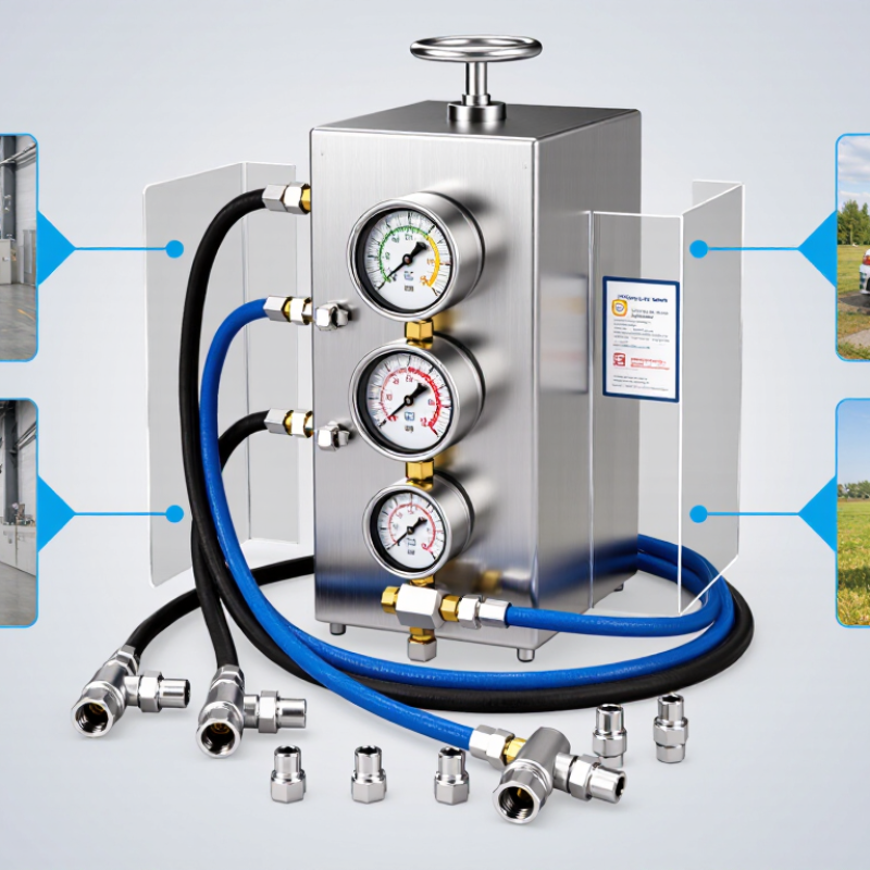
| Pressure Range | Testing capacity should cover the maximum working pressure of the hose assemblies, with suitable margin for proof and burst testing. Many hydraulic hose standards use proof pressures around 2 times working pressure and burst pressures around 4 times working pressure, but the applicable hose standard must be confirmed. | Check the maximum rated test pressure, pressure units, pressure transducer range, and whether the system supports MPa, bar, psi, or interchangeable displays. | Insufficient range can make the tester unsuitable for the intended hose class and may encourage unsafe overloading of the equipment. | Required |
| Pressure Accuracy | A calibrated pressure-measuring system is required for dependable test results. Accuracy should be stated as a percentage of full scale or of reading, together with the operating temperature range. | Request the instrument accuracy specification, calibration certificate, calibration interval, serial-number traceability, and calibration method. | Accurate measurement supports repeatable acceptance decisions and reduces the risk of approving weak assemblies or rejecting compliant assemblies. | Required |
| Applicable Hose Test Standards | ISO 1402 is widely used for hydrostatic testing of rubber and thermoplastic hoses. ISO 19879 covers test methods for hydraulic fluid power hose assemblies, while ISO 6803 addresses hydraulic hose impulse testing. | Confirm which standards the tester can support and whether the supplied software, fixtures, and test reports use the correct test sequence and hold time. | Standards compatibility is more important than a generic pressure rating because different hose types require different procedures. | Required |
| CE Compliance for EU Buyers | CE marking indicates that the manufacturer declares conformity with applicable European Union requirements. Depending on the machine design, relevant legislation may include the Machinery Directive or Machinery Regulation, the Low Voltage Directive, and the EMC Directive. | Request the EU Declaration of Conformity, technical documentation details, risk assessment summary, operating instructions, and the list of applied harmonised standards. | CE is a regulatory conformity marking, not a general product-quality award or a universal third-party certification. | Required for applicable EU markets |
| UL and North American Acceptance | UL certification or listing is generally voluntary unless required by a purchaser, authority having jurisdiction, insurer, or applicable installation rule. Electrical construction should also be evaluated against relevant North American electrical safety requirements. | Ask whether the complete machine or only individual components have been evaluated. Verify the exact certification scope, file information, voltage, frequency, and factory configuration. | A component mark does not automatically mean that the complete pressure tester is certified. | Verify by market |
| Pressure Guard and Enclosure | The test chamber should use a robust guard, enclosure, or barrier capable of containing foreseeable hose, fitting, and coupling failures during pressurisation. | Inspect guard material, door construction, hinge strength, viewing window rating, access openings, anchoring, and resistance to ejected fragments and hose whip. | Physical containment is a primary control against stored-energy hazards during proof and burst testing. | Required |
| Guard Interlock | Where a hazardous pressure condition can exist, opening the guard should prevent pressurisation and should initiate a safe pressure-release sequence where required by the risk assessment. | Test the interlock under realistic conditions. Verify that bypassing is difficult, faults are detected where required, and the machine cannot restart unexpectedly after guard closure. | An interlocked guard is stronger than a warning label because it links physical access control to the machine safety circuit. | Strongly recommended |
| Emergency Shutdown | An emergency-stop function should be readily accessible, clearly identified, and designed to bring the equipment to a safe state. ISO 13850 provides principles for emergency-stop function design. | Verify the location and color of emergency-stop devices, reset behavior, pressure isolation, depressurisation response, and prevention of automatic restart. | Emergency shutdown should stop hazardous motion and energy generation; it should not be treated as a substitute for guarding or isolation procedures. | Required for risk-controlled designs |
| Hydraulic Isolation and Depressurisation | The system should provide controlled pressure release, isolation from the pressure source, and protection against trapped pressure in the test chamber and hose assembly. | Check bleed valves, dump valves, lockable isolation points, pressure indicators, residual-pressure warnings, and the time required to reach a safe pressure level. | Residual pressure can remain dangerous even after the pump stops, especially when disconnecting fittings or opening the enclosure. | Required |
| Overpressure Protection | A pressure-relief device or equivalent protective control should limit pressure to a safe value consistent with the machine design and test procedure. | Verify relief-valve setting, tamper resistance, discharge routing, maintenance instructions, and whether the relief device is independent of the normal control interface. | Overpressure protection reduces the likelihood of catastrophic equipment failure caused by control faults or incorrect settings. | Required |
| Hose Restraint and Fixture Security | Test fixtures should securely retain hose ends, adapters, and couplings and should control hose movement in the event of rupture or fitting separation. | Confirm compatible thread standards, rated adapters, restraint cables or sleeves, fixture load ratings, and the maximum assembly length and diameter. | Incorrect adapters or inadequate restraint can create projectile and hose-whip hazards even when the pressure source is correctly rated. | Required |
| Control-System Safety | Safety-related control functions should be designed according to the machine risk assessment, with suitable monitoring of critical devices such as guard switches, emergency stops, and pressure sensors. | Request the safety-circuit diagram, component safety ratings, fault-response description, reset logic, and validation records where applicable. | Control reliability is essential when software or automatic sequencing is used for high-pressure testing. | Required for automated systems |
| Electrical Protection | Electrical construction should include appropriate protective earthing, overcurrent protection, enclosure protection, wiring identification, and compatibility with the destination voltage and frequency. | Verify electrical schematics, rated voltage, frequency, short-circuit protection, ingress-protection rating, grounding method, and conformity documentation. | Electrical compliance affects safe installation, inspection, serviceability, and acceptance by local authorities. | Required |
| Noise, Leakage, and Fluid Containment | The design should control hydraulic-fluid leakage and provide suitable containment, drainage, and housekeeping access. Noise exposure should be evaluated where pumps or intensifiers operate frequently. | Check drip trays, drain points, seals, hose routing, fluid compatibility, spill-control provisions, declared sound-pressure levels, and required personal protective equipment. | Leak prevention protects personnel, equipment, floors, and the environment while reducing maintenance downtime. | Recommended |
| Test Data and Traceability | Test records should identify the assembly, test pressure, pressure-hold time, date, operator, instrument identification, and pass/fail result. | Evaluate electronic export formats, audit trails, barcode or serial-number input, report locking, backup options, and the ability to print or export results without proprietary restrictions. | Traceable records support customer acceptance, internal quality systems, warranty investigations, and regulatory audits. | Strongly recommended |
| Calibration and Maintenance | Pressure sensors, gauges, relief devices, interlocks, and emergency-stop circuits require documented inspection and maintenance according to the risk assessment and manufacturer instructions. | Confirm calibration procedures, spare-part availability, service access, recommended inspection intervals, and the process for handling failed calibration results. | Regular verification preserves measurement reliability and keeps safety functions operational over the equipment life cycle. | Required |
| Operator Documentation and Training | Operating instructions should cover setup, approved hose types, maximum pressure, test procedures, emergency response, depressurisation, inspection, and maintenance. | Request manuals in the destination language, safety labels, training materials, lockout or isolation instructions, and documented operator competency requirements. | Clear documentation helps prevent incorrect fixture selection, unsafe access, and operation beyond the tester’s design limits. | Required |

.svg)