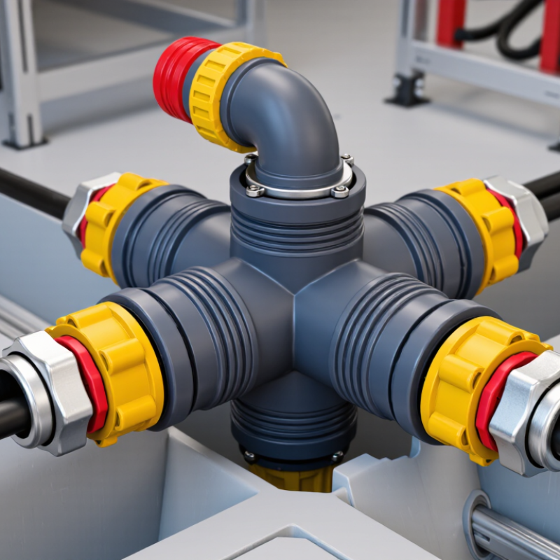
| Equipment Type | 15 kV-class, 200 A loadbreak junction | An insulated medium-voltage connection assembly that provides one or more separable cable interfaces for connecting, branching, parking, or isolating energized feeder cables under specified loadbreak conditions. |
| Nominal System Voltage | 15 kV | Intended for distribution systems with a nominal line-to-line voltage of approximately 15 kilovolts. The exact permissible system voltage depends on the equipment design and applicable standard. |
| Maximum Rated Voltage | Typically 15.5 kV for a 15 kV class | Defines the highest system voltage for which the junction is designed. The nameplate and product documentation should be used for the final rating. |
| Continuous Current Rating | 200 A | The maximum continuous current the properly installed junction can carry without exceeding its specified temperature limits under rated conditions. |
| Loadbreak Current Rating | 200 A, when specifically rated | Allows an approved separable connector or elbow interface to interrupt current within its defined loadbreak rating. The junction itself should not be used as a general-purpose switching device unless expressly designed for that function. |
| Power-Frequency Withstand | Commonly 34 kV for a 15 kV class | Indicates the insulation withstand capability during a specified alternating-current test. The actual test voltage and duration must be verified against the applicable standard and product documentation. |
| Basic Insulation Level (BIL) | Commonly 95 kV peak | Represents the impulse-voltage withstand level used to coordinate insulation performance against lightning and switching surges in the distribution system. |
| Operating Frequency | 50 Hz or 60 Hz | Suitable frequency is determined by the electrical network and the assembly’s tested design. Many medium-voltage distribution systems operate at either 50 or 60 hertz. |
| Connection Interface | 200 A separable loadbreak interface | Provides a standardized interface for compatible insulated elbows, plugs, bushings, parking accessories, or test accessories. Compatibility must be confirmed by interface dimensions and ratings. |
| Typical Configuration | Single-sided, two-way, or multi-way junction | The number of connection ports is selected according to the feeder arrangement, such as straight-through connections, loop feeds, taps, or temporary cable parking. |
| Conductor Compatibility | Specified cable size and conductor material | Compatible conductor ranges vary by connector design, cable insulation diameter, conductor material, and compression or shear-bolt termination method. Cable dimensions must be checked before installation. |
| Insulation System | Molded elastomeric insulation with conductive shielding | Provides electrical insulation and a controlled conductive shield around the interface. The shield helps manage electric-field stress and supports safe grounding practices. |
| Shielding and Grounding | Grounded screen or shield connection required | The conductive shield and grounding arrangement help limit touch potential and maintain proper electrical-field control. Installation must follow the manufacturer’s grounding instructions and local safety rules. |
| Primary Purpose | Flexible feeder interconnection | Used to connect distribution cables, create a loop or branch point, facilitate sectionalizing, and provide a practical interface for maintenance or system reconfiguration. |
| Protection Function | Not normally a circuit breaker or fuse | A loadbreak junction provides connection and isolation capability; it normally does not detect faults or automatically interrupt short-circuit current. Separate protective equipment is required. |
| Fault-Current Capability | Design-specific momentary and short-time ratings | Fault withstand values are separate from the 200 A continuous and loadbreak ratings. The required momentary and short-time current ratings must be verified for the network fault level. |
| Applicable Reference | IEEE Std 386 and relevant local requirements | Separable insulated connector systems for medium-voltage distribution commonly use IEEE Std 386 as a technical reference. The applicable edition, utility requirements, and local electrical codes should be confirmed. |
| Installation Environment | Indoor or outdoor distribution equipment, design-dependent | The enclosure, sealing system, contamination performance, and environmental rating determine whether the junction is suitable for pad-mounted, vault, switchgear, or other installation locations. |
| Key Safety Requirement | De-energize, test, ground, and follow approved procedures | Loadbreak capability does not eliminate arc-flash, shock, or induced-voltage hazards. Only qualified personnel using compatible tools, accessories, and procedures should operate or install the equipment. |

.svg)