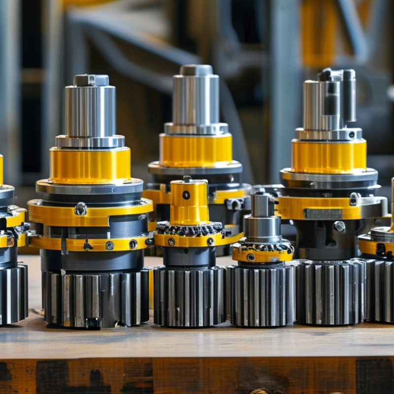
| Definition | A bevel gear is a toothed gear with teeth arranged on a conical surface. It transmits rotary motion and torque between intersecting shafts. | It is suitable for machinery that requires a change in the direction of power transmission. |
| Typical Shaft Arrangement | Most bevel-gear drives connect shafts at a 90-degree angle, although other intersecting shaft angles are possible. | The arrangement allows designers to redirect power where a parallel-shaft gearbox would not fit. |
| Operating Principle | When the driving bevel gear rotates, its teeth mesh with the mating gear and transfer force along the conical tooth surfaces. | Continuous tooth engagement provides controlled speed and torque transfer when the gears are correctly aligned and lubricated. |
| Speed and Torque Relationship | For an ideal gear pair, output speed is approximately proportional to the ratio of input gear teeth to output gear teeth. Torque changes in the opposite direction, excluding losses. | A larger driven gear can reduce output speed while increasing available output torque. |
| Common Gear Ratio Range | Single-stage bevel gear sets are commonly designed for moderate ratios, often approximately 1:1 to 5:1. The practical range depends on tooth geometry, load, speed, and noise requirements. | Multiple stages may be used when a larger overall reduction is required. |
| Straight Bevel Gears | The teeth are straight and extend radially toward the apex of the cone. | They can be relatively simple to manufacture and are often used at low or moderate speeds, but they generally produce more noise and vibration than spiral designs. |
| Spiral Bevel Gears | The teeth are curved and engage progressively rather than all at once. | They normally provide smoother, quieter operation and greater load-carrying capability, making them useful for higher-speed industrial drives. |
| Zerol Bevel Gears | These gears have curved teeth with a spiral angle close to zero. | They combine some characteristics of straight and spiral bevel gears and can be selected when moderate smoothness and controlled axial loading are required. |
| Hypoid Gears | Hypoid gears are offset spiral bevel gears whose shafts do not intersect. Their tooth surfaces involve significant sliding as well as rolling contact. | They can provide compact right-angle drives and increased gear-pair contact, but they require suitable lubrication and careful thermal management. |
| Directional Flexibility | Bevel gears can redirect rotary power through a selected shaft angle, commonly 90 degrees. | This helps simplify layouts in conveyors, pumps, mixers, machine tools, material-handling equipment, and processing machinery. |
| Mechanical Efficiency | Well-designed and properly lubricated bevel gear drives can achieve high mechanical efficiency. Exact efficiency depends on tooth form, ratio, speed, load, lubrication, alignment, and bearing losses. | High efficiency can reduce energy losses and operating costs compared with less suitable transmission arrangements. |
| Load Capacity | Load capacity is determined by tooth bending strength, surface durability, material, heat treatment, face width, pitch, speed, and lubrication. | Industrial systems can be sized for heavy torque transmission when the gear set, shafts, bearings, and housing are engineered as one system. |
| Axial and Radial Forces | Bevel gear tooth geometry generates radial forces and, especially in spiral designs, axial thrust forces. | Shafts and bearings must be selected to withstand the combined forces without excessive deflection or premature wear. |
| Noise and Vibration | Straight-tooth bevel gears generally have more abrupt tooth engagement. Spiral-tooth designs engage gradually and can reduce noise and vibration. | Lower vibration supports improved operator comfort, equipment reliability, and product quality in precision machinery. |
| Typical Materials | Common materials include alloy steels, carbon steels, stainless steels, cast irons, bronze, and engineered polymers. Material selection depends on load, speed, temperature, corrosion exposure, and noise requirements. | The correct material can improve wear resistance, fatigue life, corrosion resistance, or weight efficiency. |
| Heat Treatment | Industrial steel bevel gears may use carburizing, nitriding, induction hardening, or through-hardening to improve surface durability and fatigue resistance. | Heat treatment can extend service life, but it must be controlled to limit distortion and preserve tooth accuracy. |
| Lubrication | Gear oil or another application-appropriate lubricant reduces friction, removes heat, and protects tooth surfaces from wear and scuffing. | Correct lubricant viscosity, cleanliness, level, and replacement interval are essential for dependable operation. |
| Alignment Requirement | Accurate shaft positioning, bearing support, backlash, tooth contact, and housing rigidity are critical to proper bevel gear operation. | Misalignment can cause uneven contact, noise, heat generation, tooth damage, and shortened service life. |
| Space Efficiency | A bevel gear set can transmit power through a right-angle arrangement without requiring two separate transmission systems. | This can reduce the installation footprint and simplify compact machine layouts. |
| Maintenance Needs | Routine maintenance generally includes checking lubricant condition and level, inspecting seals and bearings, monitoring temperature and vibration, and verifying tooth contact when necessary. | Condition monitoring helps identify misalignment, overload, lubrication problems, and progressive wear before a major failure occurs. |
| Main Advantages | Right-angle power transmission, compact arrangement, controllable speed reduction, high torque capability, and availability of smooth spiral-tooth designs. | These characteristics make bevel gears a practical choice for many industrial power-transmission systems. |
| Main Limitations | They can be more sensitive to alignment and manufacturing accuracy than simple spur gears. Spiral and hypoid designs may also create axial loads, sliding losses, and greater lubrication demands. | They should be selected only after evaluating load, speed, temperature, noise, maintenance access, and installation accuracy. |
| Selection Criteria | Important inputs include transmitted power, input and output speed, torque, shaft angle, duty cycle, shock loading, service factor, operating temperature, noise limits, available space, and expected service life. | A complete application analysis helps ensure that the gear set and supporting components are correctly rated. |

.svg)